
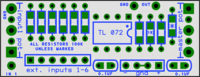
This utility circuit provides basic mixer (6 channel), isolation, level shifting, and/or level boosting capabilities in a tiny panel-mounted package.
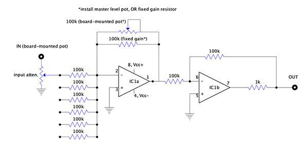
Not limited to mixing, the circuit is based on a standard configuration of 2 inverting op-amps in series (so, non-inverting in sum), which provides many configuration options. Default values give unity gain, but can be modified to provide signal boost, or level shifting.
Circuit configuration based on Ken Stone's DC Mixer; this version is physically shrunk and adds the SMT options & onboard pot mounting scheme.
(Because of the flexible nature of the design, values and quantities may vary)
* there are pads for two 47pf bypass caps (SMD0805) on back of board if necessary to supress self-oscillation, optional in almost all instances.
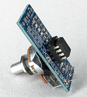
The PCB is intended to be supported by a panel-mounted pot, chicklet style. Two mounting options are provided, using either the master level control pot on one end of the board, or the first input pots on the other end.
All off-board input pots will need to be wired to the input resistors as voltage dividers: signal in to one side of the pot, ground to the other side, and the wiper to the input resistor(s) on the PCB.
You can omit the master pot entirely if a fixed overall gain is desired, simply omit the master pot and install a 100k resistor in the * position for unity gain. Higher values for * will result in greater-than-unity gain — for instance, 120k will amplify signals by 1.2, if you want to boost 1v/oct CVs to work with Buchla (you could even use a 200k trimmer in the variable pot slot, so you could precisely adjust to a preset boost).
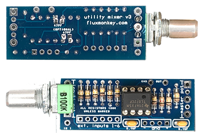
[Mounting pot on channel end, fixed master gain, through-hole components]
Options are also provided for either through-hole or SMD parts (except for the IC, which is TH only). If you’ve been leery of hand-soldering surface-mount parts, this is an excellent intro project to try your hand at soldering them — it's easier than you think.
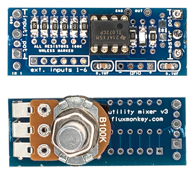
[Mounting pot (right angle) on master end, SMD components]
Both the signal inputs and power connections can be fitted as 0.1" headers. However, check the fit of both the headers and their connectors, to make sure there's enough clearance with all your parts and mounting scheme.