Looney Board
LooneyBoard #1 is the first in a series of PCB boards aimed at
SDIY and noise musicians.
This project originated in a series of workshops
I've presented, based heavily on Nic Collins Hardware Hacking book
and other net resources:
In those workshops, we built circuits on solderless breadboards. Those
work great for experimenting, but are a little too delicate for gigging.
The LooneyBoards provide an easy way to transfer your designs to an easy-to-build,
reliable platform.
LooneyBoard#1 supports: 6 oscillators based on a 40106; 4 more gated
oscillators on a 4093; a digital ringmod using a 4011 or similar, and
an LM386 audio amp... plus some utility mixer arrays and a prototyping
area. See below for details about each section.
I'm also working on documenting specific projects
you can build with these boards... more to come!
This is the first of at least 2 "voice" boards; we're also
working on a "sequency" board and a "modifier" (filter)
board. They can be used individually or in combinations to create a wide
variety of sound-producing instruments or effects boxes.
Overview
The LoonyBoard 1 includes several powered circuits based on CMOS chips,
plus some additional utilities. These circuits can be built separately
or combined as building blocks for complex sound/noise devices:
- Hex Oscillator—6 simple oscillators built using a 40106 hex inverter
chip
- Quad Gated Oscillators—4 oscillators with switching inputs, using
the 4093 quad nand gate
- "Ring" Modulator—digital effect takes 2 signals in and outputs
a related but separate tone
- Amplifier—utility amplifier so you can hear the other circuits via
a speaker
- Mixers—three passive circuits, each of which can mix 4 signals together
into one
- Prototyping area—space to add your own outboard components
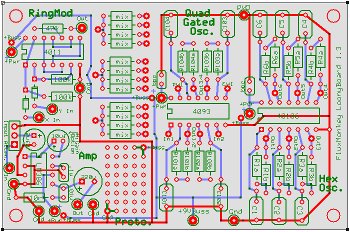
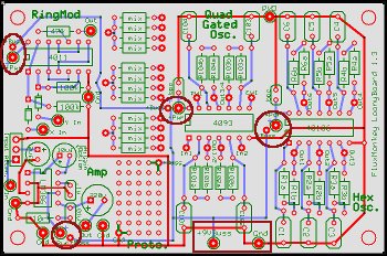
Power
IMPORTANT: YOU HAVE TO CONNECT POWER TO EACH MODULE IN ORDER FOR THEM
TO WORK. Each of the four powered circuits on the board has its own power
connection (labeled "+Pwr", and circled on the board diagram
below). The board also has a "Power Buss" so you can link all
those +Pwr ins to a single 9volt battery.
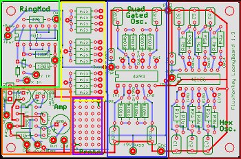
USUALLY, you'll want to use the Buss to power all the modules from a
single battery; it's easier. To do that, you must CONNECT JUMPERS BETWEEN
THE "+Pwr" AND "+Buss" CONNECTIONS NEXT TO EACH
MODULE, like this:

Then, you can connect a single battery to the "+9VBuss" and
"Gnd" connections on the bottom center of your board. All of
the modules will then powered by the single battery. On a standard 9v
battery clip, the red wire is + and the black wires is – or ground.
There are a couple of reasons why you might choose NOT to connect one
of the modules to the common power buss:
- The amplifier consumes a lot of power. You might want to put it on
its own battery to conserve juice.
- If either of the oscillators is "power starved" (run on
just a volt or two), it'll start to glitch out in unpredictable and
perhaps interesting ways... so putting a voltage divider pot between
the buss and one of those power ins can be useful
- You can use the output of an oscillator to provide power to the other
oscillator chip... again, producing unpredictable results, sometimes
good, sometimes not so... YMMV.
Ground connections are handled on the board, and are common for all modules,
even if you use separate power.
40106 Hex Oscillators
The Hex Oscillator section has 6 identical oscillators built around the
6 inverters of a 40106 chip; each oscillators uses one of the inverters
plus 2 resistors and a capacitor. The resistance/capacitance relationship
determines the frequency of each oscillator: smaller resistor/capacitor
combinations will give higher pitches; big resistors/caps will be lower.
Typical starting values for audio oscillators might be a 0.1uf capacitor
and 100k total resistance.
Each of the oscillators is essentially the same:
| Schematic |
PC Board |
 |
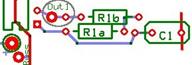 |
- Space is provided for 2 series resistors (a and b): one is typically
a variable resistor to change the frequency of the oscillator, the second
one can be use to provide a minimum resistance (running the chip w/
zero resistance can sometimes produce Bad Results).
- Total resistance is the sum of both resistors; I often start with
2.2k for one resistor and a 100k potentiometer (pot)for the other;
these values are not critical.
- Besides pots, there are lots of things to use as variable resistors:
photocells;
ribbon
controllers, force-sensing
resistors... or a couple of wires stuck in a glass of tap water
and moved back & forth.
- The capacitor is laid out to support different sizes of caps by providing
2 places to connect one of the sides... use the hole on the outside
of the board for one side of the cap, and either of the other 2 for
the other lead.
- If you’re using an electrolytic cap (useful for really slow oscillators,
like for rhythm machines), make sure the negative side goes to ground
(hole closest to the outside of the board).
- The output of the oscillator is in between the chip and the "b"
resistor—the big pad is the one you'll usually use, but I added a second
which can be useful if you're adding "touch pads".
4093 Quad Gated Oscillators
The Quad Gated Oscillator section is very similar to the Hex Osc; it
has 4 identical oscillators built around the NAND gates on a 4093 chip,
with the same configuration of 2 resistors plus a capacitor per oscillator.
| Schematic |
PC Board |
 |
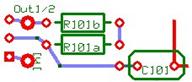 |
- The difference with the 4093-based oscillators is the presence of
an "input", implemented via pins 1, 6, 8, and 13 of the chip
(labeled "In1", "In2"etc.). If the input of an
oscillator is high (plus voltage over about 2.2v), the oscillator will
turn on; if it is low or tied to ground, it will not oscillate.
- If the input is left "floating" (not connected to either
power or ground), it may still pick up enough voltage from the circuitry
around it to allow some sound to come thru (it can get a little unpredictable,
which might be good or bad depending on your perspective). This might
be an opportunity to try out touch pads, or an antennae.
- The outputs are the larger pads towards the center of the chip (near
pins 3, 4, 10, and 11). There wasn't enough room to lable them individually,
but output 1 is nearest to R101; output 2 is near R102, etc..
4011 "Ring Modulator"
This is kind of a single-purpose circuit; it's not a true ring modulator,
but uses digital logic mixing to approximate the classic.
- CD4030 or 4070 can be substituted for the 4011.
- Inputs can be any square wave signal. You could try non-square waves
as inputs (even external signals boosted via the amp), but YMMV.
Passive Mixers
These provide a couple simple ways to combine multiple signals. You
can mix multiple Oscillator outputs into one signal... either via a simple
resistor network, or through a diode matrix.
- If the resistors are the same value (I usually use between 47k and
100k), you'll get an even mix of all the input signals.
- You could also run each oscillator through a simple volume
control before tying them together through the mix network, so you
can mix in different levels of each oscillator.
- You can tie the outputs of multiple resistor mixers together, if you
need to mix more than 4 sources.
- The sound of the diode mixing will be considerably different, with
more interaction between the mixed signals... this often works better
with just a couple of inputs.
386 Amplifier
CMOS circuits will not drive a speaker out directly, so I added a small
amplifier based around the LM386 chip.
- It's not a high-fi amp by any means, but it will let you hear what
you're doing.
- The default gain of the circuit is about 20x, and the CMOS circuits
will overdrive it to distortion; you'll probably want to use the volume
control to cut the input level.
- There is an optional 10uf capacitor (marked "HiGain Option")
you can install to boost the gain to 200x... way too much if you're
amplifying the oscillators, but it can be used to amplify an external
signal to levels you could use with the CMOS stuff.
Prototyping Area
Empty space for whatever you want. Three pads on one corner supply power
from the buss; three in the other corner provide grounds. Some possibilities:
- One more CMOS chip; maybe a 4017 decade counter set up as a sequencer?
- Use a DIP
switch to select different caps on some of the oscillators?
- Homebrew vactrols
(LED/photocell combinations) to provide voltage control of the oscillators
- Some kind of filter or other sound modifier:
General Tips
- The oscillator circuits here are pretty standard, but are explored
in detail in Nic Collin's wonderful
book. Get it. Read it.
- I always try out designs on solderless breadboards... once I have
a configuration I like, then I commit it to a PCB. The main purpose
of these PCBs is to enable you to build custom instruments in a physically
"robust" format, so they perform more reliably. But explore
first, then commit your designs to solder.
- Nothing says you HAVE to use all 10 oscillators, just because they're
available. Sometime less is more, sometimes more is more...
Application Notes:
Among other projects, LooneyBoard1 can be used to build Aurthur Harrison's
Cacophonator:
Use the HexOscillator section, but DO NOT link it's power to the Power
Buss. The unusual power structure (C5, RV5, R10, C7, and the switches)
can be built in the Proto area; also the output resistor/caps on U1E &
U1F (R13/14, C10/11--don't omit these... even tho you don't hear them
directly, they "wobble" the chip and are an essential part of
the sound).