LM386 "Little Gem" Amplifier
This project is based on the Little Gem amp (http://runoffgroove.com/littlegem.html).
It’s a 1/2-watt amplifier similar to a bunch of tiny practice guitar
amps; it uses a single integrated circuit and just a handful of components.
The version we’ll build has a single “gain” control; this is like the
drive control on a guitar amp, turning it up will give a “dirtier”,
more distorted sound.
We’ll use this as an introduction to building circuits on a breadboard,
as well as introducing a couple new kinds of components and schematic
symbols. We’ll also be using this amp to listen to the oscillators
and stuff we’ll start building next session.
Here’s the schematic for the Little Gem (from the runoffgroove.com site); it uses a couple of new symbols:
- Ground: the down-pointing striped triangles represent
the ground connection, which just means they’re all connected
together. The input, output, and power supply (-9v) all have
an assumed connection to ground that is not shown in this
schematic.
- Integrated Circuit: in this case, it’s the triangle
labeled 386. It has 8 “legs” for connections, and the numbers
next to the connections represent those legs. (pin 7 is not
used, so it’s not shown).
- Electrolytic capacitors: the 100uf and 220uf caps
have little plus signs on one side, which means they are polarized
and have to be put in right way around.
|
 |
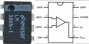
Integrated circuits are just little building blocks that have
more complex circuitry inside them. The ones we’ll be using
come in small rectangular packages with 8, 14, or 16 leads.
This package is called a “DIP”, meaning dual inline
pins. The LM386 has 8 pins:
- IC pins are numbered in order, counter-clockwise from the
little dot in one corner. Occasionally the dot is missing,
in which case the little half-moon notch will indicate which
end is “up”.
- The line diagram shows how the inner circuit is arranged
(different for various ICs). The labels give information
about the pins In this case, “Vs” on pin 6 indicates the
power supply (Voltage) connection; pin 4 is ground.
|
 |
Preliminary: how breadboards work:
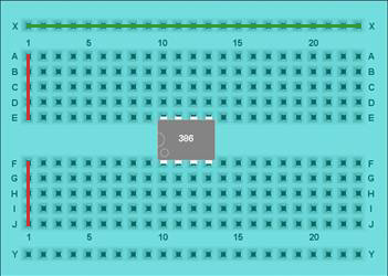 |
- Breadboards have holes connected together in patterns; you
stick components in the holes to connect them together
- Each set of 5 vertical holes (red line in
this pic) are connected together; so if you stick one lead in
hole “A1”, and another in “E1”, they’re connected.
- The channel in the middle is not connected; so “E1” and “F1”
are not connected together. That channel is the same width
as most integrated circuits, so we’ll usually place ICs straddling
that channel so you can make separate connections to each side.
- The outside horizontal “buss” lines (green) are also connected
together; a lot of times, you’ll use one of those lines for
power and the other for ground. Some breadboards have 2 busses
on each side, which can be handy--just remember which one is
ground and which is power.
|
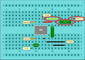
Build on Breadboard
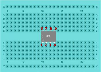
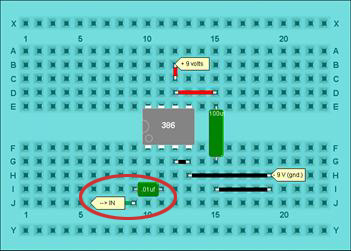
Step 1: Place the 386 op-amp. Pin numbers start to the
left of the dot/halfmoon on one end, and go counterclockwise:
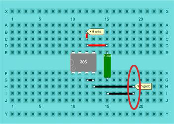
Step 2: Add the ground connections, including the 100uf
power filtering capacitor. The diagram shows using one of the
vertical rows (19) for ground, but you could also use the horizontal
bus row going across the bottom. The cap is polarized; the side
marked with a minus sign goes to ground; the other side goes to pin 6 of the IC:
Step 3: add the input capacitor (.01uf; may be marked
“103”); it is not polarized:
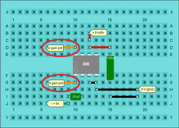
Step 4: add the gain control (connections to your 5k pot.):
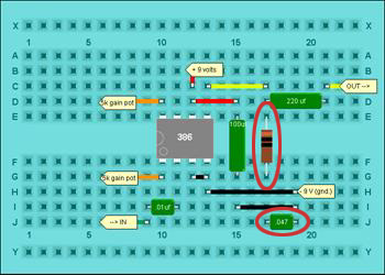
Step 5: add the 220uf output cap; watch the polarity (negative
side is the output to your speaker; positive to pin 5 of the LM386):
Step 6: add the output bridging resistor/cap.:
That’s basically it. Test it out:
- Connect a contact mike/piezo element (little brass disk) to the
input: red wire to the “In” connection on the .01uf cap; black wire
to ground.
- Connect the gain pot if you haven’t already.
- Connect a speaker: one side to the 220uf cap, the other side to
ground.
- Connect power via the 9v battery clip: black wire to ground, red
wire to the +9v connection (IC pin 6).
- Tapping on the contact mike should produce sound in the speaker.
Coolness. If it doesn’t work at first, first make sure that none of
the components, or the battery, is getting hot--if it is, you have a
short someplace, meaning there’s a direct connection between power and
ground. Disconnect the batter and find the short.
If nothing’s hot and it’s still not working just start tracing your
connections one at a time; I usually start with the power connection,
then ground, then with the input and work my way from left to right.
My most frequent mistake is just mis-counting the breadboard holes and
thinking I had connected something when I hadn’t.
Building the same circuit on Perfboard:
You could leave your amp on the breadboard; we’ll use it to amplify
the oscillators and stuff we’ll start building next session. Breadboards
circuits are a little delicate, especially as we unpack/pack each week,
and you might want to free up some of that space for more fun stuff.
One solution would be to transfer your amp to perfboard. You have a
small perfboard in your kit; basically you stick the components through
the holes and solder them together on the back. Here’s the layout:
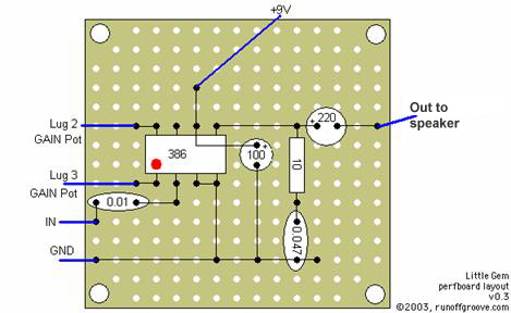
- This is a view from the top side of the board. Components go on
top, and the wires are soldered on the bottom.
- Use the IC socket from your kit (ICs are a little heat sensitive,
so it’s safer to solder the socket and plug the IC in after). Start
by soldering pin #7 of the socket (it’s not used otherwise) just to
hold it into place.
- Next, lay down a piece of wire to use for the ground connection…
strip a piece of the thin wire, and just solder it down at either
end of the perfboard
- Add the rest of the circuit in basically the same order as we did
on the breadboard: ground connections, 100uf cap, input etc. Make
each connection one at a time and then solder; double-check your work
as you go.
- For the ground connection to pins 3 & 4 you’ll need a short
piece of wire; most of the others you’ll be able to just bend the
component lead into place and solder it down.
- Remember that the picture is from the top--when you turn over the
board, everything will be kind of mirror-imaged. Go slow.
We will need some kind of little amp starting next week. If this seems
like too much trouble at this point, other alternatives would be: