
The oscillators we’ve been building produce a square wave... beeeeeeeeep. By itself, it’s a little harsh, and kind of boring. Modulating one oscillator with another spices up that basic sound some; we’ve also been varying the pitch (frequency) by changing our resistors and capacitors. This week we’ll change two other aspects of the sound: volume and timbre (tone). This will allow us to add some dynamics to our heinous din. We’ll also start to talk about ways to add controls and switches, to turn our circuits into more playable instruments.
Volume is easier to understand. The more juice coming out of the oscillator, the louder the sound. So we change the volume by choking off some of the juice, using a voltage divider or volume control. They’re really the same thing, only one is preset at a certain amount of “choke”, and the other is variable.
A voltage divider is basically a resistance that goes across the output of your oscillator (between the signal and ground); at some point in that resistance, you tap off some percentage of the signal.
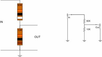
The incoming signal gets soaked up by the 2 resistors in series (100k total); most of it gets soaked up by the first 90k resistor, and about a tenth of it is left over for the 10k resistor... so if you put 2 volts in, and tapped off 10% from the smaller resistor, you'd get about .2 volts out.
(BTW, those happen to be good values if you want to take a signal meant to drive a speaker and tone it down to plug into an amplifier... for instance, if you wanted to plug Fred into your 365 amp...).
Changing the values of the resistors would change how much voltage comes out... if you used two equal resistors, it would divide the input voltage in half. And it’s the ratio between the two resistors that really determines how much gets through... not the absolute values.
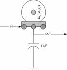
A volume control works exactly the same way:
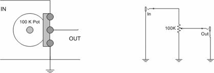
The only difference is that as you turn the knob on the pot, you change the ratio between the two resistances (the resistance of the pot between the left end and the wiper, and between the right end and the wiper), so the amount of juice that gets thru changes between 0 (wiper to ground) and 100% (wiper to the input end).
Another option is to use our trusty photocells as one a variable leg of the voltage divider:
It won’t go all the way to zero, because that second resistor will always be there, keeping your output from hitting ground (no signal)... but it’ll get close. You can adjust the lower resistor value to match the specific photocell, but 10k is probably a good starting place.
Finally, back in Intro to Oscillators, we mixed several oscillator signals together by feeding them into resistors, and tying the other end of each resistor together. That’s a mixer. Now, you can add a volume control to each input (between the signal and the mixer resistor), and control the volume individually for each channel:

:
The pots are our volume controls, and the 47K resistors are the mixers.
Those values are not particularly critical. If you’re buying pots for
an audio mixer, you should buy “Log” pots (the other option is “Linear”),
but this is also not critical. We can talk how your ear hears volume,
and psychoacoustics, on Saturday.
Anyway, if you connect 3 separate oscillator outputs into each of the mixer inputs, you can now fade them each one in and out independently. Look out Behringer.
Volume controls lower the volume (or attenuates) a signal. Filters attenuate certain frequencies of a signal. We’ll talk about two types of filters today: Passive low-pass and passive high-pass. Low pass filters (LPFs) allow lower frequencies to get through, but attenuate higher frequencies. High-pass filters (HPFs) do the opposite: they filter out lower frequencies, but let the high ones get through. Passive means there is no amplification--they can cut out certain frequencies, but they can’t boost others.
You might be thinking that frequency equals a certain note, like A = 440 Hz... and so a filter would cut off notes above or below a certain pitch. Like chopping off half your piano keyboard. Not quite. The simple way to think of it is like the bass/treble controls on the stereo--when you turn down the bass control it’s like a high pass filter, the treble keeps coming thru but the bottom end gets less thumpy. In reality, it’s a little more complicated than that.
Our oscillators are generating square waves, and although a square wave has a certain pitch, on another level it’s made up of a bunch of different frequencies all mixed together. (Technically, it’s a combination of all of the odd harmonics of the fundamental pitch...). So when we apply a filter, it cuts out some of those component frequencies, and actually changes the shape of the wave. In fact, a low-pass filter kind of rounds the sharp corners of the square wave, which sounds like it smoothes out or mellows the tone of the oscillator. This is easier to hear than it is to explain; on Saturday I’ll bring an oscilloscope so we can look at the waves and see how the shape changes, and what that sounds like.
So, let’s build one and listen. Here are the schematics for the two kinds of filters:
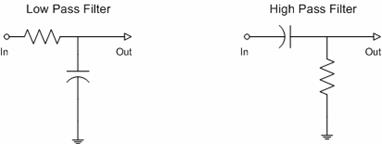
It doesn’t get much simpler than that, eh? Oh and BTW, here we are again with that damnd resistor/capacitor network thing. Anyway, you can build this on the breadboard, or just with alligator clips. Start with the low pass, using a .1uf cap, and a 100k pot for the resistor. Connect one of your oscillators to the filter input, and the filter output to your amp.
As you turn the pot, you should hear the filter “sweep”--you’ll recognize the sound of countless cheezy synth solos, from rock to techno. The filter is cutting off frequencies above a certain point--as you sweep the control, the frequency where the filter starts filtering raises or lowers.
I usually just arrive at resistor and capacitor values by trial and error, swapping in parts and choosing by ear. But if you want to get scientific, here’s a table showing the corner frequency for various capacitor and resistor values:
.01uf
| .047uf
| .1uf
| .47uf
| 1uf
| | |
|---|---|---|---|---|---|
1k
| 15.9 kHz |
3388 Hz |
1592 Hz |
339 Hz |
159 Hz |
|
5k
| 3.18 kHz |
678 |
319 |
68 |
31 |
|
10k
| 1.59 kHz |
338 |
159 |
34 |
- |
|
20k
| 796 Hz |
169 |
79 |
- |
- |
|
30k
| 531 |
112 |
53 |
- |
- |
|
40k
| 398 |
84 |
40 |
- |
- |
|
50k
| 398 |
68 |
32 |
- |
- |
|
60k
| 318 |
57 |
27 |
- |
- |
|
70k
| 228 |
48 |
22 |
- |
- |
|
80k
| 199 |
42 |
20 |
- |
- |
|
90k
| 177 |
37 |
- |
- |
- |
|
>100k
| 159 |
33 |
- |
- |
- |
|
Frequency is in hertz (abbreviated Hz. kHz=kilohertz=1,000 Hz); middle A is supposed to be 440 Hz. We don’t hear below about 20 Hz or above 20 kHz (worse if you listen to a lot of loud music). The “corner frequency” is the point where the filtering starts to happen), and it’s the same for RC combinations in either the low-pass or high-pass filter. Heres a little online calculator to calculate corner frequencies of RC filters, if you want to try some different RC values. You can also read more theory online--check Wikipedia or google “passive low pass filter”. They’re used a lot in speaker crossovers, to get the high frequencies to the tweeters and the lows to the woofers.
Well, I ran out of time so I didn’t get my little lecture on switches written up. The reason I wanted to talk about switches is to prepare for turning our bread-boarded circuits into instruments... we’re going to need some way to control our circuits that’s easier and more reliable than shoving wires into holes in a breadboard.
Anyway, here’s my outline, maybe we’ll just talk through this at the session. See you then.
|
Credits & References:
|