
This week we’re building our first oscillators, hot damn. Oscillators produce AC signals, which we can amplify and hear as tones. Oscillators can also control other oscillators, making more complex tones. We’ll do both of those things, then we’ll put them in fancy spray-painted boxes, sell them to suckers on e-bay, and retire to Vermillion. Hot damn.
The basic oscillator building block we’ll start with is based on the 40106 integrated circuit. We used a different integrated circuit (the 386 chip) last week to build our amps; it had only one circuitry block in it, a single analog amplifier (the right-pointing triangle on the schematic). The 40106 has 6 different digital circuitry blocks, called “Schmitt Triggers” or inverters. Each inverter can be turned into its own oscillator just by adding a resistor and capacitor (remember the resistor/capacitor bend we did to Fred?... same principal). So you can get 6 oscillators out of one chip.
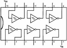
Here’s a picture of the 40106, showing the pin numbers and the 6 inverters:
BTW, most chips do different things and have different pin-outs. You can always download the data sheet for a chip to get this info (google for “data sheet” and the chip number). Data sheets also often have sample schematics that can help get you started using a new chip.
In this case, VDO (pin 14) is the positive power connection, VSS (pin 7) is the negative or ground. These connections are not always shown on schematics you find on the internet, they’re just assumed. Schematics also just take a shortcut and show the circuit elements that are being used (they don’t show the whole chip); in this case, each of the triangle thingies w/ the circle on the tip is an inverter. Sometimes they won’t even tell you what pins to use--check the data sheet if you ever need to know which pins are which, or where the power goes. On chips like this with multiple elements, all the inverters on the chip are the same, so you can pick whichever one makes the layout easiest.
So that’s the IC, here’s the schematic for our basic oscillator, using 1 inverter, 1 resistor, & 1 capacitor:
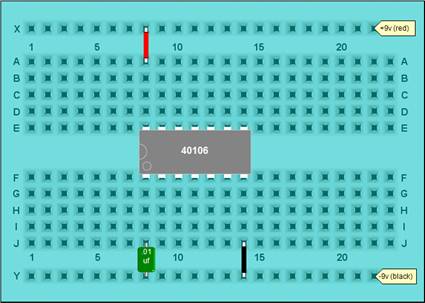
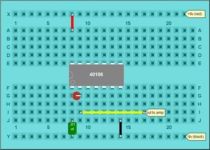
This is one of those schematics that omits the power connections, and just shows the basic circuit building blocks (although it does show the pin numbers). Here’s how to breadboard it… first place the chip, wherever you have room, and add the (assumed) power lines:

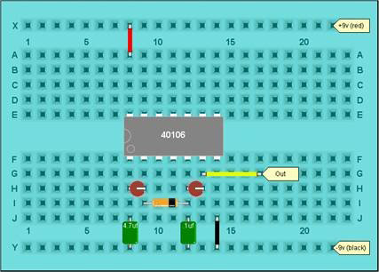
Then add the capacitor (.01 uf, sometimes marked 103, to start with):
Then add the resistor; try 100k (brown-black-yellow) as a starting point… since it’s going across pins 1 and 2 of the IC and there’s not much room, fold over one lead so both leads are sticking out in one direction, and trim them so you can stand it on it’s end:
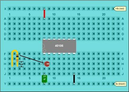
Then connect the signal to your amp (don’t forget the ground, too) and listen:
BEEEEEEEEEEEEEEEEEEEEEEEEEEEEEEEEEEPPPPPPPPPPPPPP.
Hot damn. Oscillation! Once you’ve got a beep, you can start playing. Remember changing Fred’s speed by varying the timing resistor? We can do the same thing here. Replace the resistor with a photocell. Or wire in a pot (variable resistor) to control the pitch. Or, hold the two resistor leads in your fingers and squeeze to change your skin resistance. Or a combination. Play.
You can also change the capacitor value… swap in some different ones and see what happens. Sometimes the particular resistor/capacitor combination will be either too high or too low to hear… oops. Try something else. Somewhere between .001 and .1 uf should be OK.
Hokay, since more is better, we’ll build 2 more oscillators right next to the previous one. Like this:
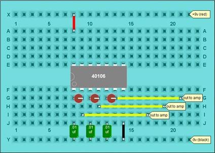
Check each oscillator out one at a time, by listening to each output separately. If you use the exact same resistor/capacitor values, each oscillator should sound about the same; if you used different R/C combinations they should sound different. Get all 3 oscillators happy before continuing.
But now we’ve got a problem: 3 outputs, one amplifier. We want to mix all three oscillators together. Just shorting them all together might work (for a while), but it’s a bad idea--basically, the voltages coming out of each inverter are then going back into the outputs of the others, and the ins and outs fight… and eventually someone gets unhappy and craps out. That’s why god invented Behringer and Mackie: so we could have mixers that let us connect outputs together without anyone getting unhappy. But we’re cheap and our needs are few, so we’ll just use 3 resistors as a simple mixer:
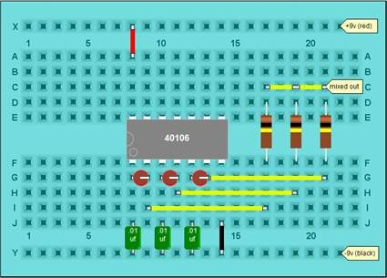
Sweet. All 3 oscillators signals are now mixed together, out to the amp. If you wanted to get fancy, you could replace the fixed mixer resistors with variable resistors (pots) connected as voltage dividers--essentially, you’d have a separate volume control for each oscillator…
Anyway, if you’ve used a couple of variable resistors (photocells or pots or touchpoints) in your oscillators, things should be getting interesting. BTW, here’s a new schemo:
It’s showing a fixed timing resistor on oscillator #1; a variable resistor (pot) on osc. #2, and a photocell (the arrows & greek y) on osc. #3. The 3 100k resistors on the right are the mixer resistors. Ov course, you might have something different by now…
So we have oscillators, and we can change their frequency by changing the values of either the resistor or capacitors. In addition to changing them manually, we can also use one oscillator to control another oscillator. Once we start stringing circuits together, one circuit controlling another circuit… oh, boy.
So we’ll set up 2 oscillators: the first one will be really slow, and we’ll use it to control the second one. Start with what you had for the last circuit, then:
The circuit should now look pretty much like this:
And here’s the schemo:
You should be able to hear the first oscillator switching the tone of the second oscillator back and forth between low to high. Try using variable resistors and start monkeying with the rate of the first oscillator, then the frequency of the second… then both.
Now, let’s speed up oscillator #1 by changing the capacitor back to .1uf or so. Now osc. #1 is switching #2 pretty fast; your ear can’t keep up with it, and instead of hearing oscillator #2 jump discreetly between 2 tones, the frequencies start to interact… this is called Frequency Modulation, or FM… this is a very powerful technique, more about it next week.
SO those are some basics: oscillators, which can be controlled manually or which can control each other. We’ve only build 3 oscillators, but the chip can do 6. A sweet setup would be 3 pairs of FM oscillators with all three outputs mixed together… speed controls on the slow oscillators, photocells on the fast ones, individual volume controls… you get the idea. You can get some pretty complex sounds with just a few basic building blocks, repeated a few times.
We’ll start working with other building blocks next week.
|
Credits & References:
|