This project is a controlled bend of a printed circuit board (PCB); it originally came from some kind of 70’s Space Robot toy. I was able to pick up a box of these surplus.
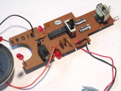
Connect the battery clip to a 9v battery, and connect the other red/black wires to your speaker. When you turn it on, the light emitting diodes (LEDs) should start to blink. The 2 pieces of metal next to the on/off switch are pushbuttons that select sounds: push one of them 1, 2, 3, 4, or 5 times to select one of 5 sounds; push and hold the other one to select some variation of a couple of those sounds.
Real circuit bending is a trial/error process of modifying existing circuits (usually toys)… Reed Ghazala (http://www.anti-theory.com/) is the “father” of circuit bending; he did a book called Circuit-Bending : Build Your Own Alien Instruments, and there’s a ton of info on the web. We’re skipping all the interesting exploration and happenstance of real circuit bending and a couple of specific modifications: changing the timing circuit, and adding alternate switches.
Fred’s brain is an integrated circuit (IC): the flat black thing with 14 legs next to the on/off switch. The IC runs off a clock: the faster the clock runs, the quicker/higher the sounds; the slower the clock, the slower/lower the sounds. There are 2 components that control the speed of the clock: a resistor and a capacitor:
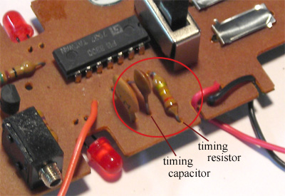
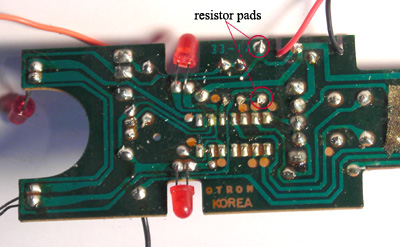
We’re going to take out the timing resistor, and replace it with various other resistances to change the speed of the clock, which will change the tones produced by the IC. To unsolder the resistor, find the pads where the resistor leads are attached on the back of the board: then heat the solder until it melts and pull or pry the resistor out, one end at a time:
After you pull the resistor, solder a couple pieces of wire in the holes where the resistor leads used to be. Careful to keep the solder on the wire and pads for the resistor, and not touching any of the nearby pads--it doesn’t take much solder to make a good connection.
Now you can connect any other resistor and see what happens. Try some other fixed resistors—connect each of the wires from where Fred’s timing resistor used to be to either side of a resistor, use clips or just twist the wires/leads together. You’ll probably need to connect a resistor, then turn Fred on and select a sound. Try different resistors, see how the sounds change. Try holding the wires between your fingers (your skin conducts electricity, but not very well—better when you sweat, so now you have a lie detector).
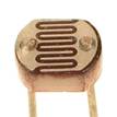
Now try connecting a photocell—that’s a resistor that’s sensitive to light:
|
Photocell: |
|
|
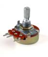
You should be able to change the sounds by covering/uncovering the face of the photocell—more light = less resistance = faster clock. Great under a strobe light. Once you get tired of waving your hand at Fred, try connecting a potentiometer (variable resistor):
|
Potentiometer: |
|
|
Connect to the center lug of the pot (the arrow on the schematic symbol) and one of the outside lugs. Twisting the shaft should change the tones. We’re using 100k pots, so you’re changing the resistance from 0 to 100k by twisting the shaft.
Finally: you’ll find that turning it all the way in one direction shuts off the sound completely… if there’s no resistance at all, the clock stops running. To prevent that, try adding a fixed resistor in series with the pot…
Resistors add together when connected in series (end-to-end), so instead of going from 0—100k, now we’re going from 20k – 120k. When I tried it, 20k seemed to be the smallest value that still made noize.
|
Credits & References:
|
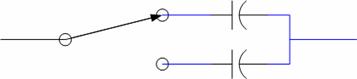
You can also change the value of the timing capacitor. Since I don’t have variable capacitors large enough to work in this circuit, I used a switch to select between 2 different capacitors. The process is the same as for the timing resistor: unsolder the capacitor from the board, solder in 2 wires, and connect the wires to the new capacitor(s). Try a few caps until you find 2 you like, then connect them to a switch so you can select between them. Here’s the schematic:
Resistors have values in ohms, and they’re labeled with colored bands that tell you how many ohms. Here’s how it works:
Our timing resistor had 4 bands: Brown, Red, Yellow, Gold, so it has a value of 12 x 10k = 120K ohms… and tolerance of ±5% (which doesn’t matter to us).
Being able to read color codes will be important when we start building stuff from scratch.