
First we’ll look at a couple simple ways of altering our oscillator circuits to make them more... um... interesting. After that, we’ll dive into a more complex active filter, which will also be an introduction to op-amps.
We’ve been seeing the variable voltage divider before—it's a really useful building block, so far using it as a volume control. You can also connect a voltage divider to your battery to create a variable voltage power supply—full on, it’ll put out 9 volts, and then you can dial it down to anything all the way to zero. Ryan got some great glitches when he added a voltage divider to the battery powering his 40106 oscillators—as the voltage went down, the chip was "starved" for power and started to crap out in unpredictable and beautiful ways. Here’s the pretty pictures:
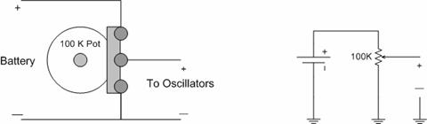
If you still have both your oscillators and 386 amp on the same power bus, you might want to put them on separate batteries—dialing down the power to the amp will probably just make it weak. Then add the voltage divider circuit to your oscillator power. Start with it on full, then slowly dial down the power until it starts to get interesting. Coming back up from zero doesn’t always work so well, the oscillators kind of need to be breathing before you and choke them off, but play around and see.
This is kind of a universal secret sauce you can do to almost any toy or circuit-bent project... digital keyboards in particular. But, you must only use this power for good, never for evil.
Jimmy Hendrix used to do something similar with a Variac and a Marshall stack, so you’re in good company. Of course, he died: DON’T PUT A POT ACROSS THE AC POWER LINES GOING TO YOUR GUITAR AMP!
I just read about this the other day, tried it out once and it seems promising, and easy. You’ll need to have both oscillator chips going. Use your 40106 for the first one, with whatever sweet-sounding setup you have—constant drone-y sounds work well. Connect that to your amp. Then set up your 4093 with a couple of bigger caps (.47–2.2uf) so it’s slow and choppy. Finally, disconnect the 9v power from the 40106, and connect the OUTPUT of the 4093 to the POSITIVE POWER pin of the 40106 (pin #14). You should hear some new kinds of interactions as the slower oscillator turns the other one on and off.
Last time we built some simple passive filters. Because they’re passive, they can only cut out part of the signal, they can’t boost, and their frequency range is limited... they’re useful, but not real versatile. Much better is an active filter, which is based around a small amplifier or op-amp. We’ll build one lifted from the Music From Outerspace "'Weird Sound Generator" Here’s your schmo:
The triangle marked LM741 is the amplifier, and you can see the signal going in one end (pin 2) and out the other (pin 6). That should look vaguely familiar from the 386 amplifier we built. Above that, there’s a couple of feedback loops--picking up the amplified signal, and running it back thru some resistors/capacitors (oh yeah, there’s that RC network thing again), and back into the inputs. The components in that feedback loop are what change the sound so it’s not just amplified, it’s filtered. Last point: unlike what we’ve done before, op-amps need two voltage supplies to run, a positive and a negative. Usually, we’d use two batteries--in this case, Ray has used R16/R17 as a voltage divider (that thing again) to create two different voltages out of one.
Anyway, here’s the board layout I used. Like before: start by placing the chip, then add your power lines, and then start working your way through, checking off components/connections as you go. I usually start at the input and add the components in the same order the signal passes through them, just to get a better idea of what’s going on, but whatever works for you.
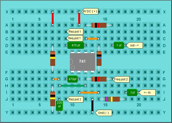
There are connections for 2 potentiometers: one for frequency (1 meg), and one for resonance (500k, with a 470k resistor in parallel--R32 / R35 on the schematic); for both of them, one connection goes to the center lug, and one to one of the outside lugs.
Test it by setting up one of your oscillators to a single tone, mid to low frequency. The output of the oscillator goes to the input of the filter; out of the filter to your amp. With the freq pot turned all the way up, it should sound pretty much like no filtering at all; turning the frequency pot down should dampen and kind of mellow the tone. Leave turned down a bit and turn up the resonance pot: you should get a kind of ringing, or more complex tone—then with the resonance up, turning the frequency knob again should shift that ringing sound up and down.
Once you’ve got the basic feel of what the filter’s doing, go back to your oscillators and start feeding it more complex tones and passages.
The filter circuit is a little more finicky as far as what values you use, but you could try swapping in a photocell for the freq pot. As always, play around.
|
Credits & References:
|